Organic Light-Emitting Diode (OLED)
What's OLED?
In this page, we will introduce the OLED (Organic Light Emitting Diode), which is attracting attention as a next-generation display.
This page introduces the structure, principle, driving method, and colorization method of OLED displays.
Structure
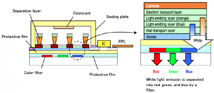
OLED (Organic Light Emitting Diode) has a structure consisting of a color filter, light-emitting layer, protective film, and separation layer formed on a glass or film substrate, filled with a desiccant, and sealed with a sealing plate made of stainless steel (SUS) or glass.
The light-emitting layer has a stacked structure consisting of an electron transport layer, a light-emitting layer, and a hole transport layer, and when the light-emitting layer is sandwiched between electrodes and a voltage is applied, the OLED emits light.
Light Emission Principle
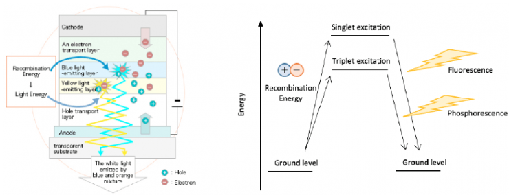
When a voltage is applied to the electrodes of an organic light-emitting diode (OLED), electrons are injected from the cathode and holes from the anode.
When the electrons and holes recombine in the light-emitting layer, the organic molecules change to an excited state, a state with high energy.
There are two types of excited states, singlet and triplet excited states, which occur in a ratio of 1:3.
When a molecule returns from the excited state to the ground state, excess energy is released as heat or light emission.
The light emitted from molecules in the singly excited state is called fluorescence, while the light emitted from molecules in the triply excited state is called phosphorescence.
Phosphorescent materials have excellent luminescence efficiency, but are inferior to fluorescent materials in terms of cost and lifetime, so fluorescent materials are generally used in OLEDs.
Drive system (PMOLED, AMOLED, Segment)
OLED (Organic Light Emitting Diode) can be classified into two types: dot-matrix and segmented.
Dot-matrix OLED is classified into passive matrix OLED (PMOLED) and active matrix OLED (AMOLED).
This section introduces each drive method.
Passive matrix OLED (PMOLED) & Active matrix OLED (AMOLED)
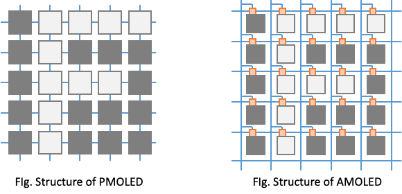
In dot-matrix OLEDs, electrodes are arranged in a grid in the X- and Y-axis directions, and pixels are placed at the intersections.
In passive matrix OLED (PMOLED), both the X and Y axes are energized to light the elements at their intersections.
Active matrix OLEDs (AMOLEDs), like PMOLEDs, light up pixels that are energized in both axes.
Each pixel has switches made of transistors and capacitors connected to it to store power, and the voltage on the X axis controls the switching on and off.
Comparing PMOLED and AMOLED, each has the following features.
Passive Matrix OLED (PMOLED)
- Simple structure and low cost
- Time-resolved dynamic drive (line sequential drive) requires higher voltage than AMOLED
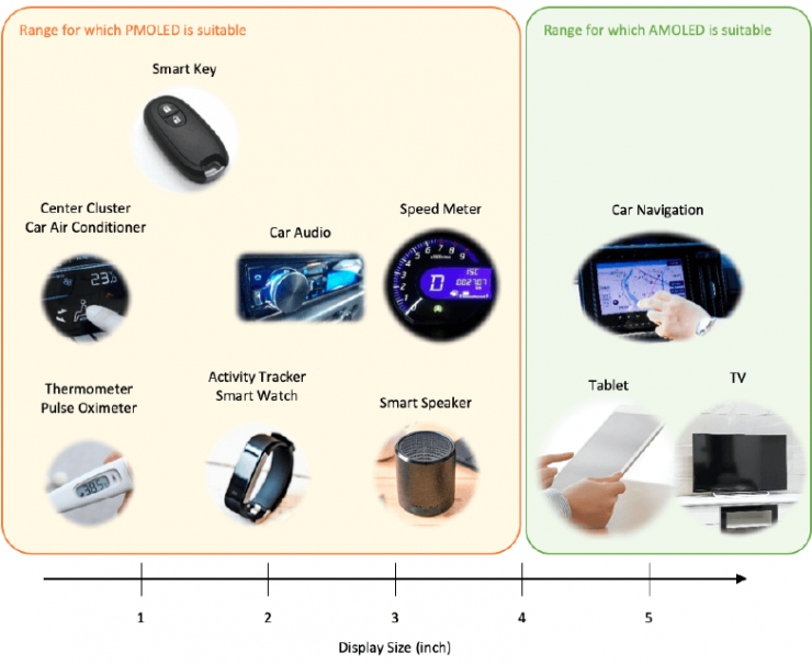
- The larger the screen, the shorter the duty ratio (time to apply voltage to each single pixel), and the lower the brightness.
Active matrix OLED (AMOLED)
- The formation of semiconductor elements in each pixel complicates circuits and manufacturing processes, and increases costs.
- Switches can prevent current leakage (crosstalk)
- Since the voltage does not drop immediately due to capacitor storage, brightness can be maintained even when the duty ratio is shortened.
Because of this difference, PMOLED is generally suitable for sizes smaller than 4inch, while AMOLED is suitable for larger sizes.
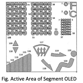
Segment OLED
Dot-matrix OLEDs consist of a grid of small rectangular elements, while the elements of segment OLEDs are formed in the shape of the picture or icon to be displayed.
Compared to dot-matrix OLEDs, segment OLEDs are more limited in the types of characters and pictures they can display, but they have the advantage of being able to smoothly express curved pictures and icons.
Each segment has a separate anode terminal, and on/off is controlled by static drive rather than dynamic drive (line sequential drive).
In static drive, a constant current is always flowing and the duty ratio (the time to apply voltage to each single pixel) is never shortened, so the brightness can be higher than in dot matrix systems.
If you want to display several types of patterns beautifully and with high brightness, segment OLED is the right choice.
Colorization technology (RGB coloring method, Color filter method)
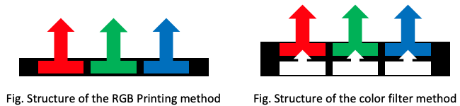
There are two methods for colorization of OLED (Organic Light Emitting Diode): the color filter method and the RGB printing method.
This section introduces the differences in structure and the advantages and disadvantages of each method.
RGB printing method
OLED (Organic Light Emitting Diode) with RGB printing method is manufactured by depositing three types of light emitting materials: red, green and blue.
Since the printing method uses three types of materials with different characteristics such as luminous efficiency and lifetime, it has the problem of increasing production man-hours and rapid changes in chromaticity over time.
However, unlike the color filter method described below, it does not attenuate luminance, so it can emit light with high luminous efficiency and high luminance.
Color filter method
In the color filter method, white light is extracted using white light-emitting material or multiple light-emitting materials and passed through a color filter to change to red, green, or blue.
In this process, luminance is attenuated by about half, resulting in lower luminous efficiency compared to the RGB printing method.
However, the change in chromaticity over time is small, and the method can maintain a clear color display for a longer period of time than the RGB printng method.
Our color OLED (Organic Light Emitting Diode) is manufactured using the color filter method, which is featured by its long life, so that our customers can use it with peace of mind.
If you would like to request a quote, a sample or demo, or have any questions about our products, please feel free to contact us via our contact form.