VFD
Self Luminous Display device with excellent visibility and contrast

The VFD is a display device that has been developed based on vacuum tube principle.
Phosphor anodes are shaped to desired pattern inside the vacuum tube.
Electrons coliding with the phosphor anode cause it to emit light.
Operating principle
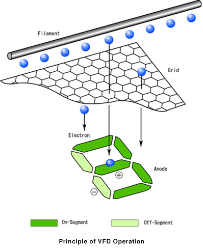
Filament
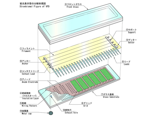
The filament consists of a very thin tungsten wire coated with barium, strontium and calcium oxides.It is held between an anchor and filament support which apply tension to the wire.Application of a specified voltage raises the temperature of the filament cathode to about 600℃ which causes thermoionic emission.
Grid
The grid is a thin stainless steel mesh formed by photo etching. When a positive voltage is applied to the grid, electrons emitted from the filament are accelerated and diffused toward the anode. When a negative voltage is applied to the grid, electron flow to the anode is cut off.
Anode
The anode consists of a conductor such as graphite, which is coated with phosphor that is formed into desired graphic pattern. Positive voltage applied to the phosphor coated anode attracts electrons which colide with the phosphor and cause light to emit.
The most widely used phosphor is ZnO: Zn which operates at low voltage and has green peak wavelength of 505 nm.
Structure